Modbus Client Configuration Landscape
Description
Modbus client configuration provides reusable connection parametrization as Orchestra Landscape entries. The parametrized clients connect to Modbus servers either via Serial or Ethernet technologies.
These entries are referenced by the Outbound and Inbound channels for Modbus: Modbus Reader Channel, Modbus Writer Channel, and Modbus Listener Channel.
⚠️ If you change anything in this landscape, you have the restart the corresponding scenario that the changes have effect.
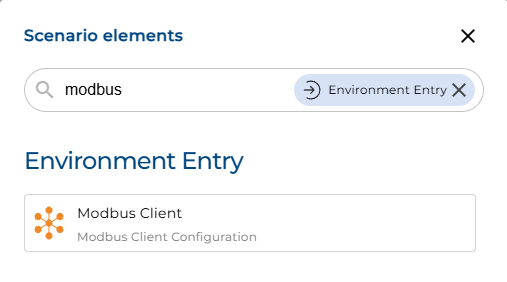
Create a new Landscape entry
Configuration
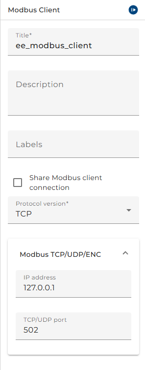
- Protocol version is the version of Modbus protocol to be used. ASCII, RTU, TCP, UDP, and ENC are listed. Please see all the supported protocol versions and their implications in Supported Protocol Versions.
The selection of TCP, UDP or ENC as protocol version enables the parameters for an IP communication protocol.
-
IP Address specifies the IP address of the Modbus device. An Internet Protocol address (IP address) is a numerical label such as 192.0.2.1 that is connected to a computer network that uses the Internet Protocol for communication. An IP address serves two main functions: host or network interface identification and location addressing.
-
TCP/UDP port specifies the port of the Modbus device if contacted via TCP/UDP protocols. By default, the protocol uses port 502 as local port in the Modbus server. One can set the local port as wished in the Modbus client. Usually, port numbers starting at 2000 are used on servers that run a non-privileged Modbus service (privileged: all ports up to 1024, non-privileged: all ports above 1024).
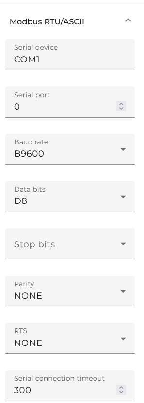
The selection of RTU and ASCII as protocol version enables the parameters for a Serial communication protocol.
-
Serial device specifies the device name for the serial communication which is typically something like "COM1" on Windows and "/dev/ttyUSB0" or "/dev/S1" on Unix systems.
-
Serial port allows to specify the port for the serial communication if the underlying technology such as RS-485 supports it.
-
Baud rate refers to the number of bits transmitted per second. It dictates the speed of data transfer. There are no methods for automated recognition of baud rates. The same baud rate must be utilized by the Server(s) and Clients connected to the bus. No specific baud rate is specified by the Modbus: typical baud rates are 9600 or 19200.
-
Data bits is the number of data bits of the serial connection for Modbus RTU. Most serial ports use between five and eight data bits. Binary data is typically transmitted as eight bits. Text-based data is transmitted as either seven bits or eight bits. If the data is based on the ASCII character set, then a minimum of seven bits is required.
-
Stop bits field is actually a stop period; the stop period of the transmitter may be arbitrarily long. It cannot be shorter than a specified amount, usually 1. Stop bits sent at the end of every character allow the receiving signal hardware to detect the end of a character and to resynchronize. One can configure stop bits to be 1, 1.5 or 2 for serial port objects.
-
Parity is a method of detecting errors in transmission. When parity is used with a serial port, an extra data bit is sent with each data character, arranged so that the number of 1 bit in each character, including the parity bit, is always odd or always even. If a byte is received with the wrong number of 1s, then it must have been corrupted. However, an even number of errors can pass the parity check.
-
RTS (Ready to Send) is the flow control of the RS-232 or RS-485 serial connection. RTS control is relevant only if you are converting to 2-wire RS485 (where the converter is a Master or a Slave) or to 4-wire RS485 (where the converter is a Slave). It is not required for RS422 which is a point-to-point system only and on which the driver is permanently enabled.