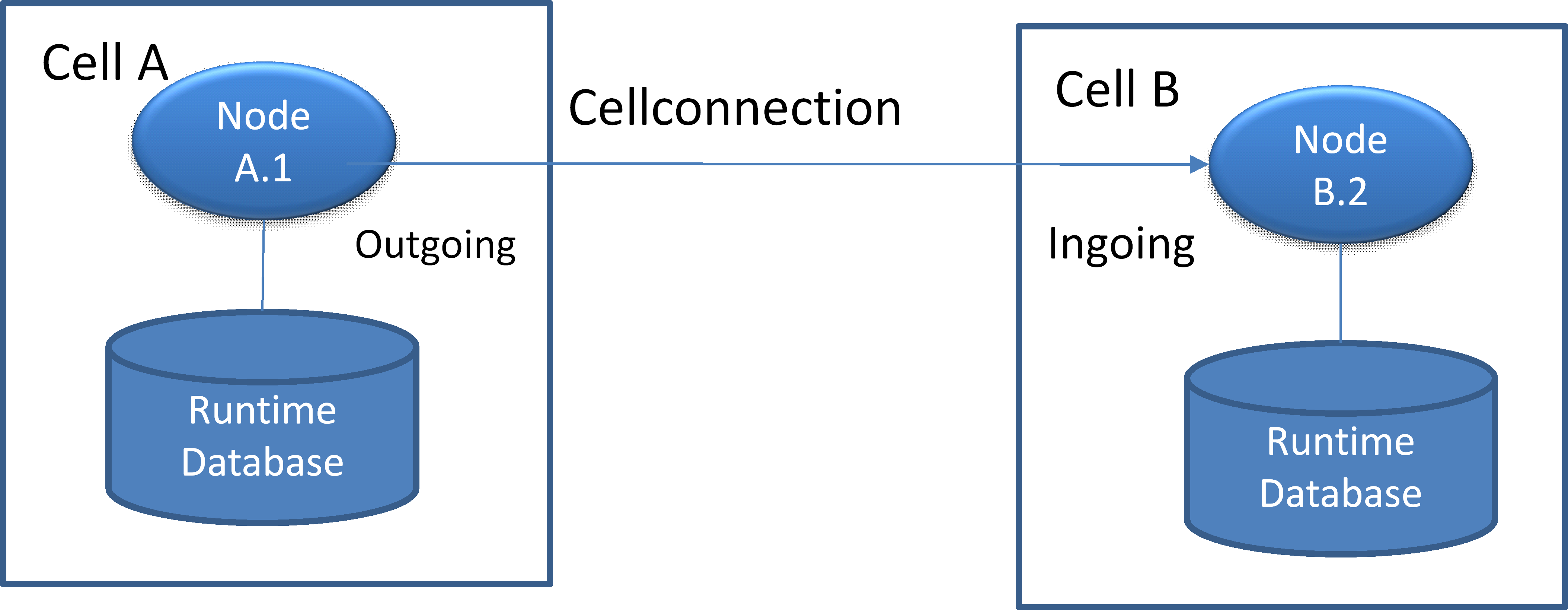
Cell Communication
This guide outlines the necessary adjustments for setting up an Orchestra Cell Communication based on the standard Orchestra installation.
Prerequisites
Before you can use cell communication, the following parameters must be configured in the environment_settings.xml file:
| Parameter | Description |
|---|---|
| Local Port | Defines the local TCP/IP port where the cell listens for incoming requests (ingoing port). |
| Pool Size | Defines the number of worker threads responsible for processing cell messages. |
Orchestra Cluster Configuration
To successfully configure the Orchestra Cell Communication, you need to set two types of parameters for each node:
- Parameters for Ingoing Connections: These parameters define which nodes are allowed to connect to the current node and send messages.
- Parameters for Outgoing Connections: These parameters define which nodes the current node will connect to and send messages to.
Step by Step
-
Navigate to
tomcat_home\webapps\orchestra\WEB_INF\classes\config\or in case of the Standalone Version\base\classes\config. -
Open the file
environment_settings.xmlusing your preferred text editor. -
Scroll down to the section
<General node settings>. -
Locate the
<Cell Communication>section and adjust the parameters as described below.
Parameter names are case-sensitive! Ensure that the names match exactly as defined in the configuration.
Configuration of a Node for Ingoing Connections
In earlier versions, node IDs were used. Since version 4.5.7.0, this is just a list of aliases. For each peer, the following entries must be maintained. <uniquename> represents the cell name contained in this list.
The following group of parameters is repeated for each element contained in the "ingoing" parameter and must be comma-separated:
| Parameter | Description |
|---|---|
peer.ingoing.<uniquename>.endpoint | TCP/IP address or hostname of the remote peer. |
peer.ingoing.<uniquename>.password | Password for authentication of the remote peer; the passwords for sending and receiving cells must match. |
peer.ingoing.<uniquename>.cell | Name of the owning cell, configured as the parameter cellname. |
peer.ingoing.<uniquename>.nodeName | Name of the node within this cell, configured as the node ID. |
<!--environment_settings.xml-->

<parameter name="ingoing" value="<list of unique names>" /> <!--value="uniquename,uniquename2,uniquename3,..."-->

<parameter name="peer.ingoing.<uniquename>.endpoint"     value="localhost" />
<parameter name="peer.ingoing.<uniquename>.password"     value="encrypted pwd" />
<parameter name="peer.ingoing.<uniquename>.cell"         value="cell" />
<parameter name="peer.ingoing.<uniquename>.nodeName"     value="node" />

<parameter name="peer.ingoing.<uniquename2>.endpoint"     value="localhost" />
<parameter name="peer.ingoing.<uniquename2>.password"     value="encrypted pwd" />
...
Sample Configuration for Incoming Cell Connection
<parameter name="nodeid" value="DMZT" />
<parameter name="cellname" value="DMZ" />
<parameter name="local.port" value="10005"/>
<parameter name="poolsize" value="5" />
<parameter name="ingoing" value="in1" />
<parameter name="peer.ingoing.in1.endpoint" value="xyu.com" />
<parameter name="peer.ingoing.in1.password" value="<password>" />
<parameter name="peer.ingoing.in1.cell" value="INTERN" />
<parameter name="peer.ingoing.in1.nodeName" value="ORC" />
Configuration of a Node for Outgoing Connections
In earlier versions, node IDs were used. Since version 4.5.7.0, this is just a list of aliases. For each peer, the following entries must be maintained. <uniquename> represents an alias for the cell name contained in this list.
The following group of parameters is repeated for each element contained in the "outgoing" parameter:
| Parameter | Description |
|---|---|
peer.outgoing.<uniquename>.endpoint | TCP/IP address or hostname of the remote peer. |
peer.outgoing.<uniquename>.password | Password for authentication of the remote peer. |
peer.outgoing.<uniquename>.port | Accept port of the remote cell. |
peer.outgoing.<uniquename>.cell | Name of the owning cell, configured as the parameter cellname. |
peer.outgoing.<uniquename>.nodeName | Name of the node within this cell, configured as the node ID. |
<!--environment_settings.xml-->

<parameter name="outgoing" value="<list of unique names>" />
<parameter name="peer.outgoing.<uniquename>.endpoint" value="localhost" />
<parameter name="peer.outgoing.<uniquename>.port" value="8891" />
<parameter name="peer.outgoing.<uniquename>.password" value="encrypted pwd" />
<parameter name="peer.outgoing.<uniquename>.cell" value="cell" />
<parameter name="peer.outgoing.<uniquename>.nodeName" value="node" />

<parameter name="peer.outgoing.<uniquename2>.endpoint" value="localhost" />
<parameter name="peer.outgoing.<uniquename2>.port" value="8892" />
...
Sample Configuration for Outgoing Cell Connection
<parameter name="nodeid" value="ORC" />
<parameter name="cellname" value="INTERN" />
<parameter name="local.port" value="8894" />
<parameter name="poolsize" value="5" />
<parameter name="outgoing" value="out1"/>
<parameter name="peer.outgoing.out1.endpoint" value="10.x.x.x" />
<parameter name="peer.outgoing.out1.port" value="10005" />
<parameter name="peer.outgoing.out1.password" value="<password>" />
<parameter name="peer.outgoing.out1.cell" value="DMZ" />
<parameter name="peer.outgoing.out1.nodeName" value="DMZT" />
Currently Not Supported: Routing Configuration
This section details all cells that do not have a direct link to the current Orchestra cell but can be reached through a route over one or more Orchestra cells.
hopcount: Defines the maximum number of intermediate cells that a packet can "hop" before it will be deleted. This is crucial to prevent infinite loops in the routing tables.
routed: A comma-separated list of all cells reachable through cell routing, including the cell names. For each peer, the following entry must be maintained:
target.<Name>.router: Defines the next router responsible for sending packets with the target <Name> to its destination (the next hop).
The following section contains a snippet of a sample configuration that can be used to establish cell communication between two standalone nodes.
Configuration via Web Services
The configuration through the environment_settings.xml file is a fundamental mechanism that requires a restart of the Orchestra runtime to take effect. To facilitate dynamic configuration of the cell system, Orchestra provides an online mechanism via a set of web services.
You can access the web service using the following URLs:
-
WSDL:
http://<host>:<port>/OrchestraRemoteService/CellCommunicationServiceMonitor/Service?wsdl -
Endpoint:
http://<host>:<port>/OrchestraRemoteService/CellCommunicationServiceMonitor/Service
This web service offers the following methods for configuration:
Configuration of Nodes
-
getNodeOverview: Returns a list of all nodes in the current cluster environment.
-
addTcpCell: Adds a new cell connection.
-
getTcpCellData: Retrieves information for all cell connections in the local node.
-
removeTcpCell: Removes a specific cell connection.
-
updateTcpCell: Updates the settings of a specific cell connection.
Configuration of Routing (Experimental Methods)
-
updateRouterEntry: Updates a router entry.
-
addRouterEntry: Adds a new router entry.
-
getRouterEntries: Retrieves all router entries.
-
removeRouterEntry: Removes a specific router entry.
Example Setups
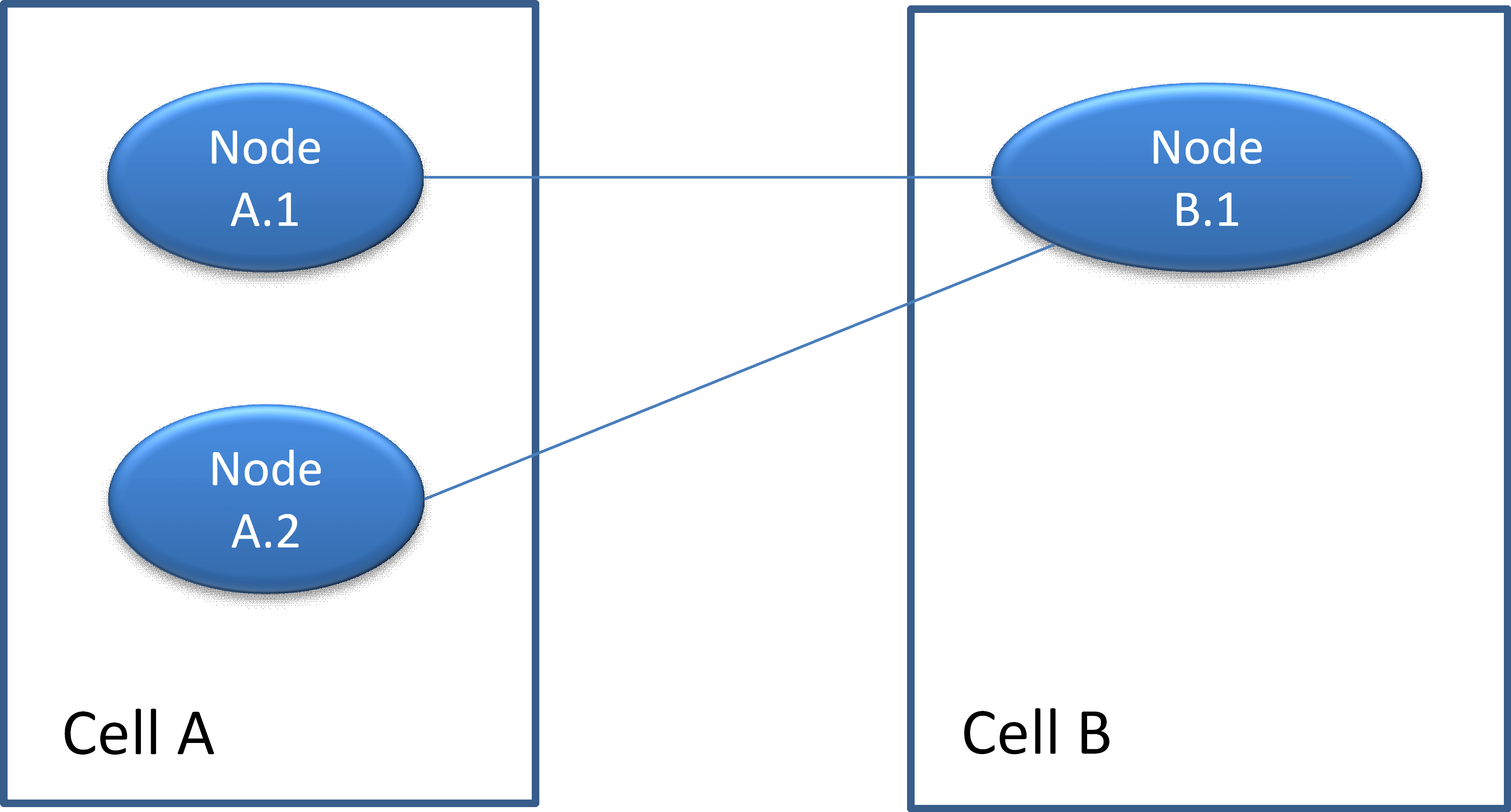
Cell A is configured as a cluster system and Cell B is a Standalone System.
Cell A has to communicate with cell B. The correct configuration for this scenario requires that each node of cell has a connection to the node B.1.
Important configuration principle: Each node in a cluster requires at least one connection to a node in the connected cell!
Cell A and cell B are configured as cluster systems.
The correct configuration for this scenario requires that each node of cell A has at least one connection to a node in cell B.
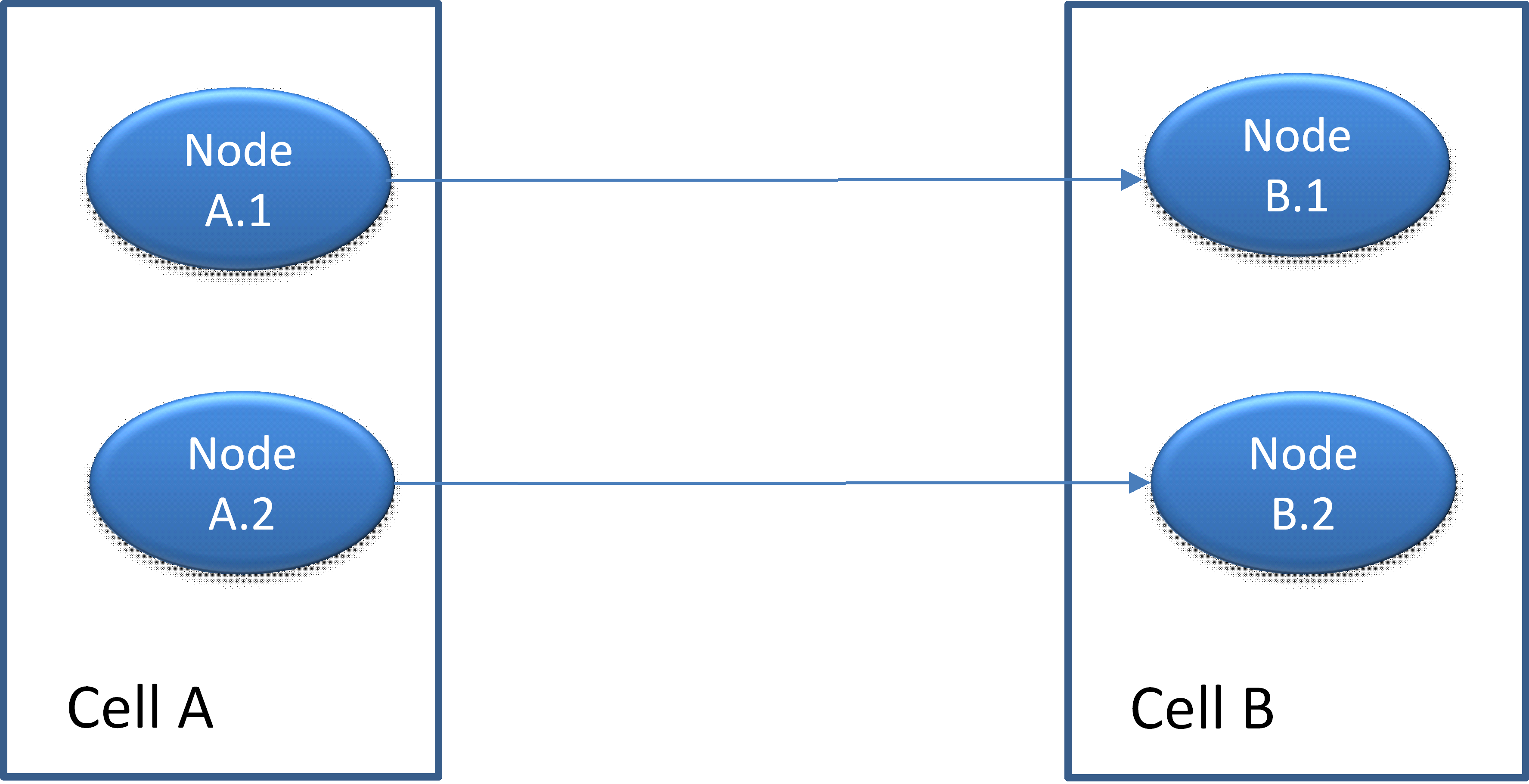
In this example the nodes from cell A and cell B are connected pairwise.
Important configuration principle: Each node in a cluster requires at least one connection to a node in the connected cell
In case that a connection between A.1 and B.1 has a failure, the cluster system tries automatically to use the node A.2 for sending cell messages to cell B.
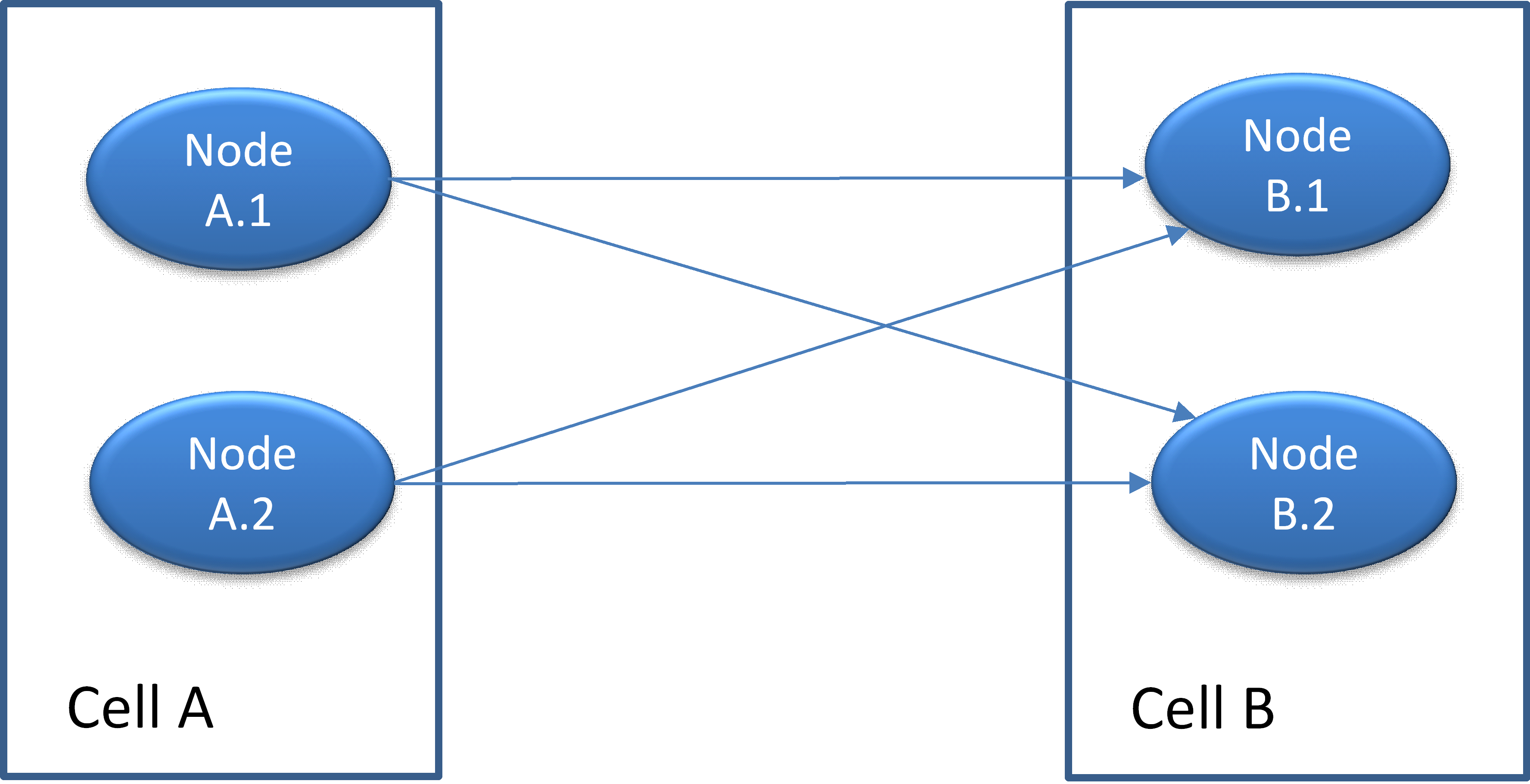
In this example the nodes are connected crosswise. When node A.1 wants to send a message to cell B one of the possible connections is taken in a round-robin manner.
Cell A and B are configured as standalone systems.